2026-10-02
In woodworking, a milling cutter can be affected by a lot more than whether its cutting edge is sharp. Cutter material and geometry matter, of course, but so do spindle speed, feed rate, the material being cut, machine condition, and even the way the cutter is used.
For manufacturers, wholesalers, distributors, and woodworking equipment buyers, these details are useful when choosing a Milling Cutter Woodwork product. A cutter that works well on one machine or material may behave quite differently somewhere else.
Tool wear also shows up in cutting quality. As the edge wears, operators may notice rougher surfaces, burning, vibration, higher cutting forces, or changes in dimensions. Finding the reason early can help avoid replacing tools before they really need to be replaced.
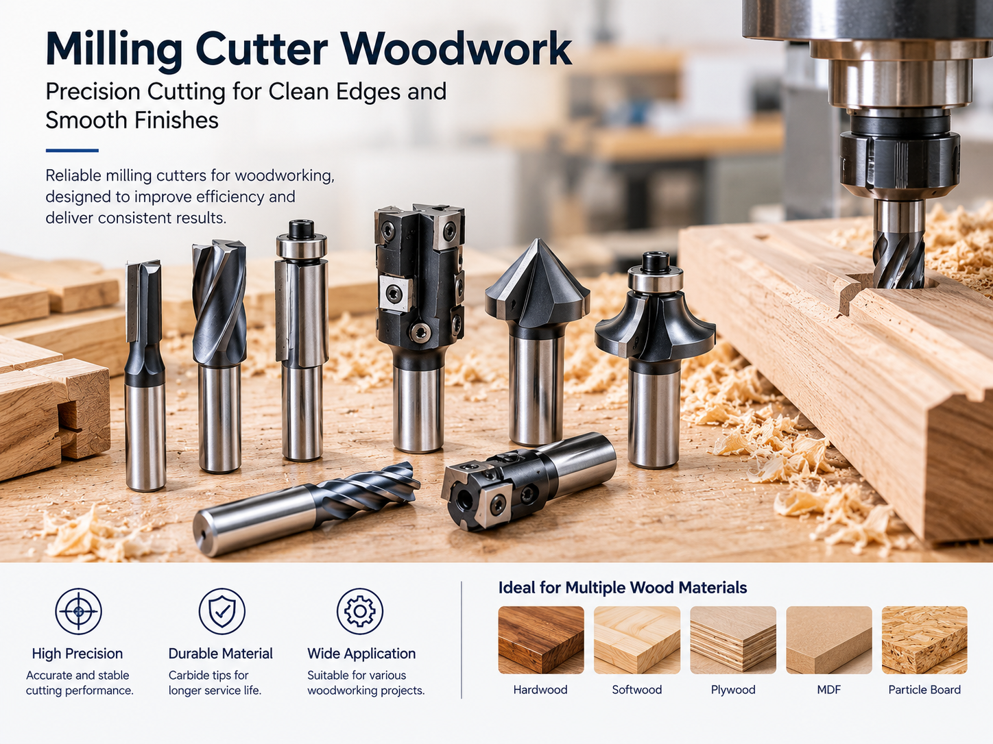
Tool life is basically the amount of usable working time a cutter provides before its performance drops below an acceptable level.
There is no fixed service life for every woodworking cutter. A tool may be considered worn when the surface finish becomes unacceptable, cutting forces increase, burning appears, or the required dimensions become difficult to maintain.
The application makes a difference, too. A cutter used occasionally for trimming does not face the same workload as one running continuously in furniture or cabinet production.
Common signs of tool wear include:
When a cutter should be replaced depends on the quality requirements and production conditions.
The cutting-edge material affects hardness, wear resistance, edge retention, and where the cutter can be used effectively.
Carbide is widely used for industrial woodworking because it offers good hardness and wear resistance. Under suitable cutting conditions, carbide cutters can keep their cutting geometry for a relatively long working period.
HSS is also used in some woodworking applications. It can be suitable when factors such as sharpening, tool cost, cutting speed, or a particular tool geometry are important.
The material choice should be based on the workpiece, cutting speed, production volume, machine capability, and required surface finish.
| Cutter material | Typical characteristics | Common consideration |
|---|---|---|
| Carbide | High hardness and wear resistance | Suitable for demanding production applications |
| HSS | Tough and relatively easy to resharpen | Useful for selected lower-speed operations |
| PCD | High wear resistance for abrasive materials | Used for certain high-volume industrial applications |
PCD, or polycrystalline diamond, can be useful when machining abrasive wood-based panels and composite materials. The actual choice still depends on the application and machine conditions.
Cutter geometry has a direct effect on cutting behavior. Rake angle, clearance angle, flute design, cutting-edge shape, and tooth arrangement all affect how chips are formed and removed.
A positive rake angle can reduce cutting force in some applications, but changing the geometry also affects edge strength. Clearance angle is important as well. If there is not enough space between the cutter and machined surface, rubbing and heat can increase.
Tooth count also changes how a cutter behaves. More teeth may suit certain finishing operations, while fewer teeth leave more space for chip evacuation.
For B2B buyers, cutter geometry should be selected according to the actual woodworking operation. Two cutters with similar dimensions may still perform quite differently.
The workpiece itself has a major effect on tool life.
Softwood, hardwood, plywood, MDF, particleboard, and laminated boards all have different machining characteristics. Natural wood can also vary in density and grain direction, even within the same workpiece. Knots, resin, moisture, and changing grain direction can increase cutting resistance.
Engineered panels bring other issues. MDF and particleboard contain adhesive and fine particles that can accelerate wear. Laminated boards may also need a cutter geometry that helps reduce chipping on the surface.
So, a Milling Cutter Woodwork product needs to match the actual material. A cutter that performs well on solid hardwood may not have the same tool life when used continuously on abrasive composite panels.
Spindle speed is measured in revolutions per minute, or RPM, and affects the cutting speed at the tool edge.
For a cutter with diameter D, the approximate cutting speed is:
where:
V = cutting speed in meters per minuteD = cutter diameter in millimetersn = spindle speed in revolutions per minuteA larger cutter has a higher peripheral speed at the same RPM.
Running outside the recommended speed range can affect heat, edge wear, chip formation, and surface quality. Excessive speed may increase heat, while unsuitable low-speed operation can increase cutting load depending on feed conditions.
For this reason, manufacturers normally provide operating parameters for their cutter designs.
Feed rate is the speed at which the workpiece moves relative to the cutter. In CNC woodworking, it needs to be considered together with spindle speed and tooth count.
The relationship can be roughly represented by chip load:
where:
f_z = feed per toothV_f = feed raten = spindle speedz = number of teethIf feed is too low for the selected spindle speed and cutter geometry, the tool may spend too much time rubbing the material and generating heat. If feed is too high, cutting load can increase and the surface may become rough.
The suitable setting depends on cutter diameter, material, tooth count, machine rigidity, and the type of cut.
Chips need somewhere to go. If they remain around the cutting edge, they can increase heat and may be cut again by the tool.
This is particularly important in CNC routing and high-speed woodworking, where a large amount of material can be removed quickly.
Flute design, airflow, dust extraction, cutter orientation, and machine setup all affect chip evacuation. A good extraction system also helps keep debris away from the tool and workpiece.
A properly selected cutter can still perform badly if the machine setup is unstable.
Spindle runout, loose tool holders, worn bearings, poor workholding, and vibration can all affect cutting performance. Runout is especially important because it can make individual teeth engage the material unevenly. One tooth may remove more material than another, which increases localized wear.
For industrial woodworking, regular checks of the spindle, collet, tool holder, and workholding system are part of sensible cutter management.
| Machine or setup factor | Possible effect |
|---|---|
| Spindle runout | Uneven tooth loading and accelerated wear |
| Poor workholding | Vibration and dimensional variation |
| Worn bearings | Increased vibration and unstable cutting |
| Dirty or damaged collet | Poor tool seating |
| Weak dust extraction | Poor chip removal and debris buildup |
| Incorrect tool projection | Increased deflection and vibration |
Wood does not behave like a uniform engineering material. Grain direction can have a noticeable effect on cutting quality.
When machining solid wood, the interaction between the cutter and grain affects tear-out and edge quality. Climb cutting and conventional cutting also produce different cutting behavior, so the choice needs to suit the machine, workpiece, application, and safety requirements.
Curved profiles, end grain, and areas where the grain changes quickly can be more difficult to machine.
For production users, testing the cutter on representative material before setting final parameters can save some trouble later.
The distance between the cutter and tool holder matters more than it may seem.
A longer tool projection makes the cutter more likely to deflect and vibrate, particularly during high-speed cutting or when machining deeper profiles.
Where possible, using only the tool length needed for the cutting depth can help keep the setup stable.
This is also useful information when ordering customized cutters. Buyers should provide the cutting depth, machine interface, spindle type, and application so the manufacturer can work toward a suitable configuration.
Burn marks usually mean that too much heat is building up around the cutting area.
The cause is not always the cutter itself. Excessive spindle speed, low feed rate, dull edges, poor chip evacuation, unsuitable geometry, and repeated contact between the tool and material can all contribute.
If a cutter suddenly starts producing burn marks after previously acceptable results, check both the edge condition and the cutting parameters. Something may have changed in the process.
Tool maintenance is a simple part of controlling production costs.
After use, cutters should be handled carefully so the cutting edges are not damaged. Dust, resin, chips, and other residue should be removed using methods suitable for the tool material and coating.
Operators should also check for chipped edges and excessive wear.
For resharpenable tools, sharpening should restore the intended geometry without unnecessarily changing the cutting-edge dimensions. Production users can set inspection intervals according to workload and observed wear.
Keeping a basic tool-life record can help as well. Recording the material, cutting parameters, machining time, and wear condition makes it easier to spot recurring problems.
Cutter diameter and price are important, but they are not enough to judge whether a tool will suit a particular application.
For OEM, private-label, and custom projects, buyers may need to discuss dimensions, tooth configuration, cutting-edge material, and machine compatibility with the manufacturer.
Useful information includes:
The more clearly the working conditions are explained, the easier it is for a manufacturer to recommend or develop a suitable cutter.
There is no single setting that guarantees long tool life.
Cutter material, geometry, machine stability, spindle speed, feed rate, chip removal, and maintenance all work together. Changing one factor can affect the others.
Tool life is also not the only thing production managers need to consider. Cutter consumption has to be balanced with cycle time, surface quality, machine productivity, and replacement costs.
The practical goal is to find operating conditions that give consistent results for the required production period.
Before changing cutters or increasing production speed, it is worth checking the whole cutting setup.
| Checkpoint | What to review |
|---|---|
| Cutter | Material, geometry, diameter, tooth count, wear |
| Machine | Spindle condition, runout, rigidity |
| Parameters | RPM, feed rate, depth of cut |
| Workpiece | Wood species, panel type, grain, abrasiveness |
| Chip removal | Flute space, extraction, airflow |
| Workholding | Stability and positioning |
| Maintenance | Cleaning, inspection, sharpening |
| Quality | Surface finish, burning, tear-out, dimensions |
Looking at these factors together can make it easier to find the actual source of a cutting problem.
A woodworking cutter is only one part of the machining process. Tool material, geometry, machine condition, workpiece characteristics, and cutting parameters all affect one another.
For buyers researching Milling Cutter Woodwork products, the useful question is not simply how long a cutter can last under ideal conditions. It is how consistently it can perform in the production environment where it will actually be used.
Start with the application, material, machine, cutting requirements, and expected production volume. From there, manufacturers can recommend suitable specifications, discuss custom configurations when needed, and establish testing procedures before larger-scale purchasing.
For woodworking businesses, this approach can make tool consumption easier to manage while keeping cutting quality more consistent across repeated production runs.
KEEP IN ToUCH

Rongcheng specializes in manufacturing and exporting wood planer bits, auger bits, shovel bits, spade bits, chisels, hammer bits and carbide, etc.
contact us
Address: Shangbutou, Qingjiang, Yueqing, Zhejiang, China
Tel: +86-577-62271200
FAX: +86-577-62276882
E-mail: [email protected]
Follow us

Carbide Hammer Drill Tools Manufacturer

 English
 русский
 Español
 中文简体
中文简体